Selection & calculation
Surge protection for LED luminaires: the driver's 4 kV against the site's 10 kV
Where surges actually come from, differential versus common mode, what the combination wave figures on a datasheet mean, when the driver's built-in withstand is enough and when a separate SPD is required, how an SPD should fail, and why Class I versus Class II changes the whole scheme.
A luminaire that sailed through driver matching and inrush sizing can still be dead by the end of its first thunderstorm season. Surge damage is the dominant electrical failure mode for outdoor LED fittings, and it has a property that makes it expensive to learn about in the field: it takes out whole circuits at once, in the same week, at sites that ran flawlessly for months. The protection question is decided at specification time, because the relevant numbers — the driver's withstand, the site's exposure, the protective device between them — are all fixed before the first pole goes up.
Where surges come from, and why "no lightning here" misses the point
Direct strikes are a structural lightning-protection problem and no luminaire device will survive one. What luminaires actually see is more mundane and far more frequent:
- Induced transients. A strike within a kilometre or so couples energy into any long conductor. Overhead supply lines and long final circuits to car parks and roadways are efficient antennas; the fitting at the end of the run receives the result.
- Utility switching. Capacitor bank switching and network reconfiguration on the distribution grid produce repetitive transients of a few kilovolts. These arrive year-round, storms or not.
- Local switching. Contactors, motors and compressors on the same installation generate bursts every operating day. Industrial sites do this to their own lighting.
The consequence: an inland site with modest storm activity but long overhead feeds can have a harsher surge environment than a coastal site fed by short buried cable. Exposure is a property of the wiring, not just the weather map.
Differential and common mode are different failures
| Differential mode (L–N) | Common mode (L/N–earth) | |
|---|---|---|
| Voltage appears between | Line and neutral | Both conductors and earth |
| Stresses | Input stage: fuse, rectifier, bulk capacitor, MOV | Insulation barriers: transformer, opto-isolators, creepage to case |
| Typical built-in withstand | 2–4 kV | 4–6 kV |
| Failure signature | Dead driver, blown input fuse | Punctured isolation — dead driver, sometimes RCD tripping, worst case a live chassis path |
Common mode is the mode that matters outdoors, because induced transients arrive between the supply conductors and true earth, and because the component it stresses is the isolation barrier — the part of the driver whose failure has safety consequences rather than only availability consequences.
Reading the numbers: the combination wave
Surge immunity figures on driver and luminaire datasheets refer to the combination wave generator of IEC 61000-4-5: a 1.2/50 µs open-circuit voltage waveform paired with an 8/20 µs short-circuit current waveform, from a defined source impedance. Two consequences follow from that definition:
- A rating is a voltage and current pair — "10 kV" on its own is half a specification. Roadway practice, following ANSI C136.2, quotes both, which is why pole-top SPDs are labelled 10 kV/5 kA or 20 kV/10 kA.
- The waveform is standardised, so figures from different manufacturers are comparable — but only if they name the same test standard. A figure derived from the ring wave test is not comparable with a combination wave figure.
Luminaire-level immunity is tested per IEC 61547 for EMC purposes, but the levels it requires are modest. The gap between what a product must survive to carry a CE mark and what a pole on an overhead-fed rural road will receive is the gap the specification has to close.
When the driver's own withstand is enough
Every reputable mains driver has some built-in protection, usually MOVs across the input, and a stated withstand in the 2–6 kV range. As a working hierarchy:
- Indoor commercial and residential — short branch circuits inside a building with its own service-entrance protection: the driver's built-in 2–4 kV is normally sufficient. Money is better spent on lumen maintenance and thermal margin.
- Light industrial interiors with heavy switching loads on the same boards: 4–6 kV differential and common mode, or a Type 3 SPD at the board serving the lighting circuits.
- Canopies, car parks, façades — outdoors but electrically short runs: 6 kV as a floor, and consider a dedicated SPD where the fittings are fed from exposed distribution.
- Roadway, area lighting, anything on long or overhead feeds: a separate SPD of 10 kV/5 kA minimum, 20 kV/10 kA where storm days are frequent or the feed is overhead for any distance. The driver's internal protection is the last line here, not the plan.
Specifying the SPD itself
The device is cheap; the decisions around it are the specification. Four of them matter more than the brand:
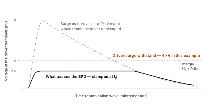
Protection level against driver withstand. An SPD is characterised by its voltage protection level Up — what it lets through while clamping the rated surge. Coordination is a one-line check that still gets skipped:
An SPD with Up = 4 kV protecting a driver with 4 kV withstand is decoration: everything the SPD passes, the driver receives.
Failure mode. SPD components are sacrificial and every SPD eventually reaches end of life. It can be built to fail open — the luminaire stays on, silently unprotected — or to fail short and disconnect the fitting, so a dark lamp marks a spent device. For maintained street lighting, fail-short (series-connected) is usually the right call: the failure is visible on a night drive-through instead of being discovered as a dead circuit after the next storm. Fail-open is defensible only where an outage is worse than lost protection, and then the SPD needs a status indicator and someone whose job it is to look at it.
Location and replaceability. In the luminaire, at the pole base, or both. A pole-base device in a fused cutout can be swapped without lifting equipment; a device inside a sealed fitting protects the wiring inside the pole as well, but its replacement costs a bucket truck visit. On high masts the answer is usually both: a coarse device at the base, a fine one in the head. Whichever is chosen, the device must be listed as a maintainable part — an SPD that dies with ten years of luminaire life remaining should be a line-replaceable unit, and its presence is worth a line in the incoming inspection checklist.
Earthing class. A Class I luminaire has a protective earth, so common-mode energy has a return path and an L/N–PE SPD can do its job — but only as well as the pole's actual earth electrode allows. A Class II fitting has no PE by design: common-mode protection there rests entirely on the insulation system's own withstand, which is why Class II roadway fittings are often specified at 10 kV insulation withstand rather than relying on any external device, and why bolting a three-terminal SPD into a Class II fitting without a design review defeats the double-insulation concept it was certified under.
What to require in a specification
- Surge withstand of the complete luminaire, differential and common mode, per IEC 61000-4-5 combination wave, as voltage/current pairs.
- The exposure class it was chosen for, in words — feed type, overhead or buried, storm exposure — alongside the environmental ratings the same site conditions drive.
- Where a separate SPD is fitted: standard (IEC 61643-11 type or ANSI C136.2), rating, Up, failure mode, and location.
- The coordination statement: Up against driver withstand, with the margin shown.
- Replaceability: the SPD named as a line-replaceable part, with the replacement procedure stated for the mounting height in question.
- For Class II fittings: the insulation system's rated impulse withstand in place of items 3 and 4.
Sources and further reading
- IEC 61000-4-5 — surge immunity test, combination wave definition and test levels.
- IEC 61643-11 — low-voltage surge protective devices, requirements and test methods (Type 1/2/3 classification).
- IEC 61547 — EMC immunity requirements for general lighting equipment.
- ANSI C136.2 — American National Standard for roadway and area lighting equipment, elevated surge withstand levels for luminaires.
- Driver and SPD manufacturers' application notes — the withstand and Up figures belong to specific parts and should come from their datasheets, not from this or any other article.