Selection & calculation
Matching a driver to an LED load, and the inrush problem nobody sizes for
Constant current versus constant voltage, why the compliance voltage window has to hold at cold start as well as hot, why paralleling strings on a CC driver fails, and the inrush current that decides how many drivers you can put on one breaker.
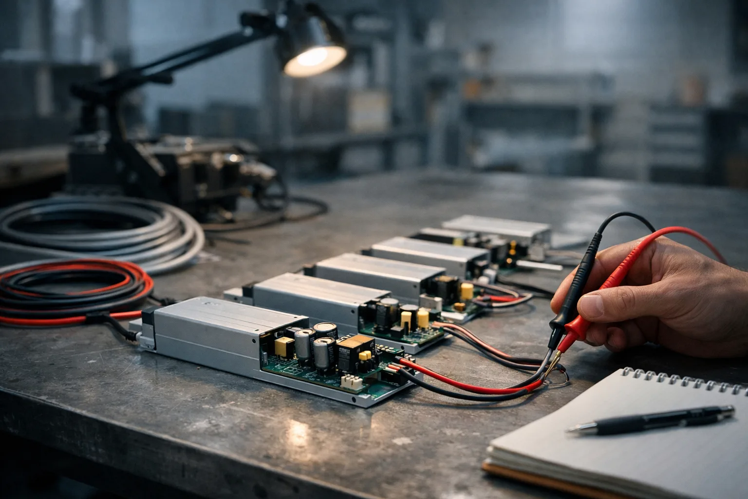
Two failures account for most driver-related callbacks. One is a compliance window that was checked at room temperature and not at −5 °C. The other is a breaker that trips every time the lights are switched on, which has nothing to do with the load current and everything to do with what happens in the first millisecond.
Constant current or constant voltage — decide what the load already has
| Constant current (CC) | Constant voltage (CV) | |
|---|---|---|
| Delivers | Fixed mA, voltage floats | Fixed 12 V / 24 V / 48 V |
| Load must provide | Nothing — the driver sets the current | Its own current limiting, usually series resistors per segment |
| Typical use | Luminaires, engines, COB modules | LED strip, sign modules, anything sold by the metre |
| Key spec to check | Compliance voltage range | Voltage drop along the run |
| Fails by | Load Vf outside the window — no start, or shutdown | Far end dim, colour shift, resistors overheating |
Which of the two a given load needs is not a preference, and the decision rules are set out in constant current or constant voltage.
Mixing them is a fast way to destroy stock. Putting a CV supply on a bare string with no limiting drives it into thermal runaway. Putting a CC driver on strip that already has ballast resistors gives an output voltage that collapses to whatever the string wants, generally somewhere useless.
The compliance window has to hold cold as well as hot
A CC driver is specified as, say, 700 mA over 27–42 V. The LED string's forward voltage has to sit inside that window under every condition the product will see. Two things move it, and they move it in opposite directions.
- Binning. Forward voltage is a distribution, not a value. A string of 12 dice at the top of the Vf bin and a string at the bottom can differ by more than a volt in total.
- Temperature. Vf has a negative temperature coefficient — a few millivolts per °C per junction. Hot, the string sits lower in the window. Cold, it sits higher.
The cold case is the one that gets missed, because prototypes are tested in a warm room. A fitting destined for an unheated warehouse, a car park or an outdoor canopy has to start at the coldest ambient it will ever see, when Vf is at its maximum and the string is still at ambient. If the top of the string's cold Vf exceeds the driver's compliance ceiling, it will not start — and it will not start only in winter, only at that site, which is a miserable fault to diagnose remotely.
Take the worst-case string Vf at the coldest specified ambient with the highest Vf bin, and the best case at maximum junction temperature with the lowest bin. Both must sit inside the driver window with margin. If a supplier cannot give you the Vf bin range they will actually ship, you cannot do this calculation, which is itself an answer about the supplier.
Do not parallel strings on one CC driver
It looks harmless: one 700 mA driver, two strings of 350 mA each. It is not, and the reason is the same negative temperature coefficient.
The two strings never have identical Vf. The one with slightly lower Vf takes slightly more current, therefore dissipates slightly more power, therefore runs hotter, therefore its Vf falls further, therefore it takes still more current. This is current hogging, it is a positive feedback loop, and it ends with one string carrying most of the current and ageing at several times the rate of its neighbour. The symptom in the field is a fitting where half the emitters are visibly dimmer and colour-shifted after a year.
If the topology genuinely needs parallel paths, they need per-path current regulation — separate driver channels, or a current-balancing arrangement — not a shared node.
Headroom, and why 80% is the usual answer
Running a driver at its full rated output is legal and unwise. The dominant wear-out mechanism in most mains drivers is the electrolytic capacitor, whose life falls roughly by half for every 10 °C rise in its own temperature. Loading a driver to 100% raises internal dissipation and therefore capacitor temperature; backing off to around 80% costs a small amount of capital and buys a disproportionate amount of life.
Two related points that get lost:
- The driver's rated life is quoted at a case temperature, at a specific measurement point — often marked Tc on the label. That figure is meaningless without the ceiling void the fitting actually lives in. A driver rated 50,000 h at Tc = 65 °C, installed where the case reaches 85 °C, is not a 50,000 h driver.
- The driver, not the LED, usually sets the luminaire's life. LED lumen maintenance is slow and predictable; driver failure is abrupt. When a supplier quotes 50,000 hours for a luminaire, ask which component that number describes.
Inrush: the specification line almost nobody writes
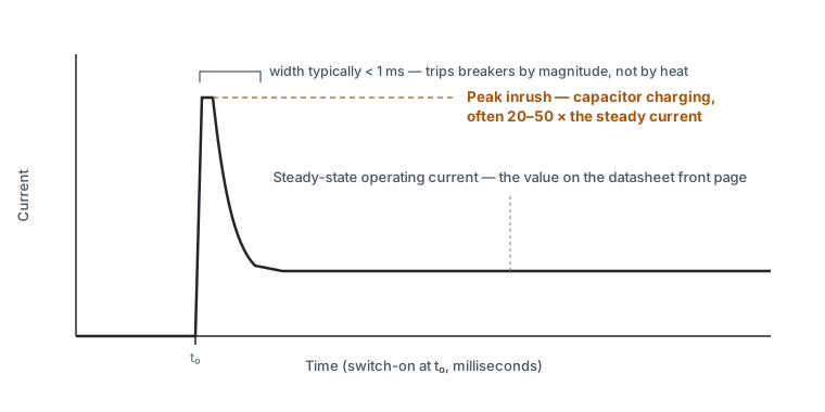
Every driver with an input capacitor draws a large, very brief current spike when energised as that capacitor charges. Peak values in the tens of amperes, lasting a few hundred microseconds, are entirely normal for a device whose steady-state draw is well under an ampere.
Steady state, a 10 A circuit will happily run a large number of small drivers. Switch them all on simultaneously through one contactor and the summed inrush can be hundreds of amperes for a fraction of a millisecond — enough to trip the magnetic element of a miniature circuit breaker, which responds to instantaneous current, not to average.
The consequences are predictable and are always discovered at commissioning:
- The lighting circuit trips on switch-on but runs fine once on.
- It trips intermittently, depending on where in the mains cycle the contactor happens to close — worst at the voltage peak.
- It gets "fixed" by fitting a larger breaker, which compromises the overload protection the circuit needed.
The correct approach is to size the number of drivers per protective device on inrush, not on running current:
- Get the driver's peak inrush current and its duration from the datasheet. Reputable manufacturers publish both; the figure is meaningless without the duration.
- Check them against the breaker's instantaneous trip characteristic — the curve type (B, C, D) determines the multiple of rated current at which it trips instantaneously.
- Where the count is too high, the remedies are: split across more circuits, use a curve type with a higher instantaneous threshold where the rest of the protection scheme permits, use relays or contactors rated for inrush, or stagger switching so groups energise sequentially.
Moving from a B to a C curve changes the earth-fault and short-circuit protection behaviour of that circuit. It is a decision for the electrical designer against the whole installation and its disconnection times, not something to be done on site because the lights keep tripping.
What to require in a specification
- Driver manufacturer and model as supplied, not "or equivalent" — flicker, inrush, dimming compatibility and lifetime all belong to the specific part.
- Compliance voltage window, with the load's worst-case Vf at the coldest and hottest specified ambient.
- Rated life with the Tc point and temperature it is quoted at.
- Peak inrush current and duration, with the maximum number of units per protective device stated for the breaker curve in use.
- Power factor and harmonic performance where the circuit or the local regulations require it.
- Surge withstand, differential and common mode — matching it to the site's exposure is its own selection problem.
Sources and further reading
- IEC 61347-2-13 — particular requirements for DC or AC supplied electronic control gear for LED modules.
- IEC 62384 — performance requirements for LED control gear.
- IEC 60898-1 — circuit breaker instantaneous tripping bands for B, C and D characteristics.
- Driver manufacturers' application notes on inrush and maximum units per breaker — the specific figures belong to the specific part and should come from its datasheet.