Selection & calculation
Constant current or constant voltage: choosing the wrong one is a wiring problem, not a preference
What each drive architecture actually regulates, the forward-voltage tolerance stack that decides whether a pairing works, why constant voltage fails at distance and constant current fails at the compliance window, and the four questions that settle the choice before anything is ordered.
Ask why a project uses constant-current drivers and the answer is often that the previous project did. It is one of the few decisions in a lighting scheme that is genuinely determined by the physics of what is being driven, and getting it wrong shows up not as a fitting that underperforms but as a circuit that cannot be wired the way the drawing says.
What each one regulates, and what it lets float
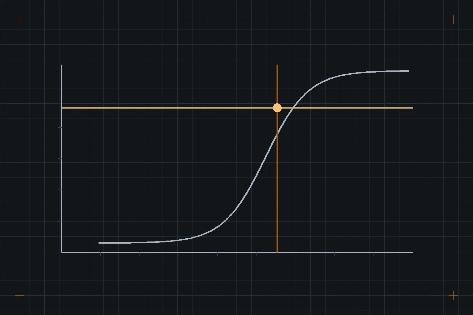
An LED is a diode. Its light output tracks the current through it, while the voltage across it is a consequence of that current, of the junction temperature and of where in the manufacturing spread that particular die fell. Any supply has to fix one of the two and let the other move.
A constant-current driver fixes the current — 350 mA, 700 mA, whatever the module needs — and allows its output voltage to settle wherever the load demands, provided that lands inside a declared range. That range is the compliance window, and it is the single most important number on a constant-current driver datasheet.
A constant-voltage driver fixes a rail — 12, 24 or 48 V — and leaves the current to be set by whatever is on the load side. That means the load has to set it: series resistors on a strip, or small regulators on each module. The driver has no idea how much light is being made.
The tolerance stack that decides a constant-current pairing
A module's forward voltage is not a number, it is a distribution. Emitters are sold in forward-voltage bins; the string voltage is the sum of however many are in series, so the spread multiplies. On top of that sits a temperature coefficient — forward voltage falls as the junction warms, typically a few millivolts per degree per emitter, which across a long string and a 50 °C rise is a substantial shift in the same direction for every unit.
Vstring,max = n × (Vf,max bin + |α| × ΔTcold)
Vstring,min = n × (Vf,min bin − |α| × ΔThot)
n = emitters in series, α = forward voltage temperature coefficient (negative), ΔT measured from the datasheet's test condition. Both ends must sit inside the driver's compliance window at the operating current, with the cold end evaluated at switch-on in the coldest ambient the installation sees.
Two failure modes come out of that arithmetic and both are field faults rather than bench faults. If the top of the range exits the window, the driver current-limits and the fitting runs dim, usually only on the units that landed in the high bin. If the bottom exits it — cold start on an outdoor scheme is the classic — the driver may not start at all until things warm up, which presents as an intermittent fault nobody can reproduce indoors. The driver compliance window calculator does this check with your numbers.
Where constant voltage fails instead
Constant voltage removes the compliance-window problem and replaces it with a distance problem. Because the current is set at the load, every millivolt lost in the conductor between driver and load is a millivolt the load does not get, and on a 12 V rail a 1 V drop is more than eight per cent of the supply. The consequence is the visible gradient along a long strip run that everybody has seen and that no amount of specifying a better strip will fix — the arithmetic is in LED strip power and voltage drop.
Two mitigations, and it is worth knowing which one you are being sold. Injecting power at multiple points along the run shortens the electrical distance without changing the strip. Moving from 12 V to 24 V or 48 V halves or quarters the current for the same power and therefore the drop. The second is nearly always the better answer where the product exists in that voltage.
They will not share. Whichever driver's regulation loop sits marginally higher takes the load until it current-limits, and the failure is thermal rather than dramatic — it shows up as one driver dying early and repeatedly. Paralleling constant-voltage outputs is a different question with its own rules, and it still needs the manufacturer's explicit permission rather than an assumption.
Four questions that settle it
- Is the load a defined, factory-built module, or is it cut to length on site? Anything field-cut — strip, tape, signage modules — has to be constant voltage, because nobody can guarantee the string length at the point of manufacture. Engineered luminaires go constant current.
- How far is it from the driver to the load? Beyond a few metres, constant current is largely indifferent to the run (the driver simply raises its output voltage to cover the cable drop, as long as that stays in the window) while constant voltage degrades continuously. Long runs argue for constant current, or for a higher CV rail with local injection.
- How many independently controlled zones? A constant-current driver is one channel. If the design has twelve fittings on four dimming groups, the driver count follows the groups, and that decides ceiling void space and access as much as it decides cost.
- What is the efficiency at the real operating point? Constant voltage with resistor-set current on the load burns the difference as heat in the load; constant current does not. On a large installation that difference is a real energy line, and it does not appear in either product's headline efficacy.
The hybrids, and what to check on them
Two arrangements sit between the pure cases and both are common enough to name. A constant-voltage rail feeding constant-current modules gives a distributable low-voltage infrastructure with proper current regulation at each fitting; check that the module's input voltage range covers the rail after the worst-case drop, and remember that each module's regulator has its own efficiency to include. Constant-power drivers hold output power rather than current across a voltage range, which suits families of fittings with different string configurations — check how the current actually varies across that range, because it does, and lumen output varies with it.
On any of these, the low voltage does not by itself make the installation SELV, and it does not remove it from the scope of your wiring regulations. Conductor sizing, protection and segregation still apply, and a 24 V circuit carrying 15 A is a fire risk in exactly the way a 230 V circuit carrying 1.5 A is not.
Sources and further reading
- IEC 61347-2-13 — safety requirements for DC or AC supplied electronic control gear for LED modules.
- IEC 62384 — performance requirements for LED control gear, including declaration of the output voltage and current ranges.
- LED module and package datasheets — forward voltage bins, the temperature coefficient, and the current-versus-flux relationship for the specific part.
- Your national wiring regulations for extra-low-voltage circuit design, conductor sizing and protection.