Calculators
Driver compliance window and headroom calculator
Checks an LED string's forward voltage against a constant-current driver's compliance window at both temperature extremes and across the binning spread — the calculation that catches the fitting which starts fine in the workshop and refuses to start outdoors in January.
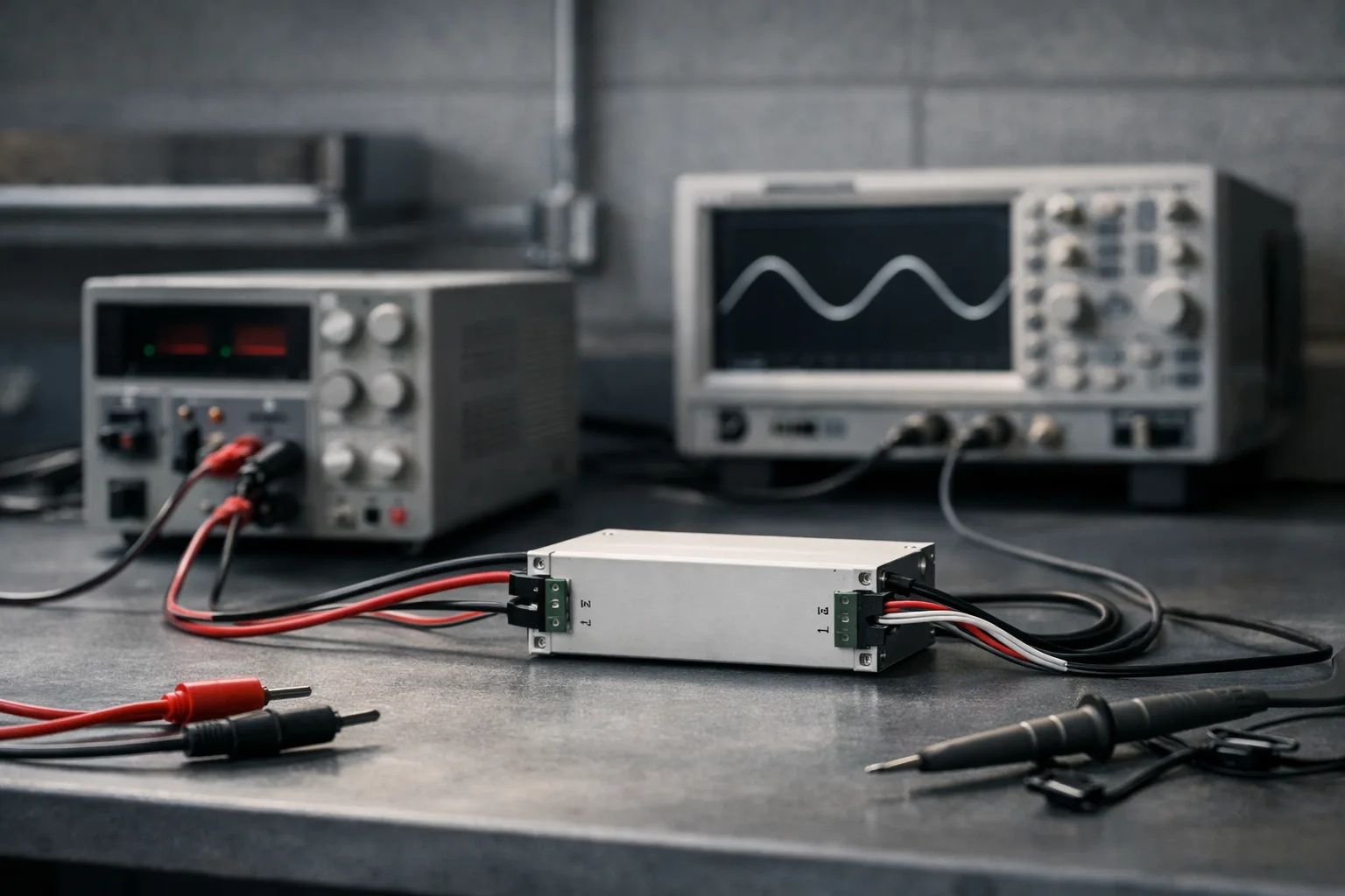
A constant-current driver holds its current by moving its output voltage. It can only do that inside its compliance window. The string's forward voltage has to stay in that window at the coldest start and the hottest running condition, with the worst binning in each direction — four corners, not one nominal figure.
Calculator
The LED string
Temperature extremes
The driver
The formulae
Why the cold corner is the one that bites
Forward voltage rises as temperature falls. At a cold start the junction is at ambient — there has been no self-heating yet — so the string demands its maximum voltage at exactly the moment the driver is trying to establish current. If that exceeds the compliance ceiling, the driver cannot deliver rated current and the fitting either fails to start, starts dim, or cycles.
The reason this reaches the field so often is that it is invisible in development. Prototypes are tested in a warm room, where the string sits comfortably mid-window. The failure appears months later, at one site, in winter, and reports as "the car park lights don't come on when it's cold" — which sounds like a control fault and is not.
Unheated warehouses, car parks, outdoor canopies, cold stores, and anything shipping to a market with a colder winter than the one it was designed in. In a heated office the cold corner rarely governs.
The hot corner, and why it is usually less dangerous
At maximum junction temperature with the lowest Vf bin, the string sits at its lowest voltage. If that falls below the compliance floor the driver is operating outside its specified range — behaviour varies, and can include reduced efficiency, regulation problems or protection tripping.
It is generally the less common failure because most drivers have a wide window at the bottom, but it becomes real when a string is designed with very few LEDs relative to the driver's rating, or when a driver is reused across a product family with different string counts.
Loading and life
Driver life is quoted as hours at a stated case temperature, and the installed case temperature is usually not the stated one. Converting between them is arithmetic, and it is the calculation that predicts which component fails first — the driver dies first works it through.
The calculator reports driver loading because it is the cheapest lever on luminaire life. Running near 100% raises internal dissipation and therefore electrolytic capacitor temperature, and capacitor life falls roughly by half for every 10 °C rise. Around 80% loading is the usual compromise: modest extra cost, disproportionate life benefit. The mechanism is covered in driver matching and inrush.
What this does not check
- Parallel strings. The model is one string on one channel. Paralleling strings on a single constant-current output invites current hogging; the driver note explains why it is a failure mode rather than a shortcut.
- Inrush. Nothing here says how many of these drivers can share a breaker. That is decided by peak inrush and its duration against the breaker's instantaneous characteristic.
- Thermal design. You supply the maximum junction temperature; whether the heatsink actually achieves it is a thermal question, answered by an in-situ measurement in the real mounting.
- Real Vf distribution. A symmetric ± spread is a simplification. Real bins are asymmetric and the mix in a given reel varies. Use the widest bin range the supplier will commit to shipping.
- Dimming. Compliance behaviour at reduced current can differ, and Vf falls with current as well as with temperature.
Sources and further reading
- LED package datasheets — forward voltage bins, temperature coefficient and the Vf-versus-current curve for the part you are actually using.
- IEC 61347-2-13 and IEC 62384 — safety and performance requirements for LED control gear, including the declaration of output voltage range.
- Driver datasheets — compliance window, rated current tolerance, minimum load, and the Tc point at which life is quoted.