Selection & calculation
The driver dies first: reading the Tc point and what it predicts about life
What the Tc marking on a luminaire means, why electrolytic capacitor life halves every ten degrees, how to turn a measured case temperature into an honest life estimate, what an in-situ temperature test must contain, and the ceiling-void conditions that quietly invalidate every figure on the datasheet.
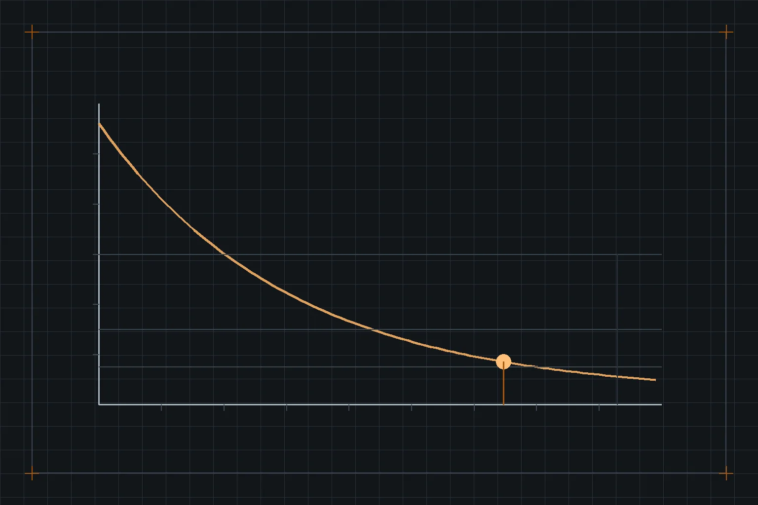
Most people specifying LED lighting have absorbed the idea that the LEDs last a very long time, and most of them have also seen an installation where a proportion of the fittings stopped working somewhere around year four. Both observations are correct. The LEDs did last; the driver did not, and the number that predicted it was printed on the fitting the whole time.
What Tc marks
Tc is a point on the luminaire, physically identified by the manufacturer — usually a marked spot on the gear tray or the housing — together with a maximum temperature for that point. It exists because the internal temperatures that matter cannot be measured in a finished product without destroying it, so the standards define an accessible proxy and require the manufacturer to declare what value of the proxy corresponds to the design being within its limits.
Alongside it sits ta, the maximum ambient the fitting is rated for. The pair works together: ta is the condition the manufacturer tested in, Tc is what you measure to find out whether your installation is harsher than that condition. A fitting marked ta 25 °C installed in a plant room at 40 °C has not been qualified for the job, whatever its IP rating says.
Why the driver is the limiting component
LED lumen maintenance is gradual and is projected from LM-80 data through TM-21 — the mechanism and its limits are in L70, LM-80 and TM-21. That process describes a fitting getting slowly dimmer. It does not describe a fitting going out, and going out is what drivers do.
The usual limiting component is the electrolytic capacitor on the driver's output or bulk rail. Its electrolyte dries out at a rate governed by temperature, and the established engineering approximation is that its useful life halves for every 10 °C rise in its own temperature. Manufacturers quote driver life as a number of hours at a stated case temperature, and that pairing is the whole claim: the hours figure without its temperature is meaningless, and it is quoted without its temperature constantly.
L = L0 × 2(T0 − Tmeas) / 10
Example: driver declared 100 000 h at Tc = 65 °C; measured in the actual ceiling void at 78 °C.
L = 100 000 × 2(65 − 78)/10 = 100 000 × 2−1.3 ≈ 40 600 h
The 10 °C rule is an approximation used across the electronics industry, not a value from a lighting standard. Where a manufacturer publishes its own life-versus-temperature curve, use that instead — it is the same calculation with better data.
Thirteen degrees of installation reality took a nominal eleven-year life to under five at continuous operation. Nothing was defective and nobody misdeclared anything. The declared figure simply belonged to a thermal condition the ceiling void did not reproduce.
What an in-situ temperature test has to contain
The only way to close the gap is to measure Tc in the installed condition, which for any large or unusual scheme is worth doing on a sample before the order is placed rather than after. A test that will survive a dispute states all of the following.
- The sensor and how it was attached. A thermocouple bonded to the marked Tc point, not held against it and not on the nearest convenient flat surface. The marked point is where the declared value applies.
- The ambient, logged, not assumed. A Tc reading without its ambient cannot be compared with anything. Log it through the run.
- Steady state, demonstrated. A stabilisation criterion — typically a rate-of-change threshold held for a defined period — and the time taken to reach it. Fittings in a confined void can take hours.
- The real mounting. The actual void depth, the actual insulation arrangement, the actual adjacent services and the actual orientation. A recessed downlight tested on an open bench is a different thermal object from the same fitting in a 200 mm void with insulation over it.
- Supply at nominal, and at the top of the tolerance band. Driver losses rise with input voltage, and a site that sits at the high end of its supply tolerance runs hotter all year.
Where insulation may be laid over a recessed fitting, the marking that matters is the manufacturer's declaration for that condition, and a fitting not declared for it must be physically prevented from acquiring it. A guard box that is fitted at first fix and removed by a subsequent trade is the most common way this protection disappears, which is why the requirement belongs in the O&M documentation and not only on the electrical drawing.
Design decisions that move Tc, in order of leverage
- Remote versus integral gear. Moving the driver out of the fitting into a cooler, accessible location is the single largest change available. It costs cable and coordination, and it converts a fitting replacement into a component replacement at year six.
- Drive current. Running emitters harder to use fewer of them raises junction temperature and driver load simultaneously. The efficacy cost of that choice is covered in luminaire efficacy versus source efficacy; the life cost lands here.
- Enclosure. Every step up in ingress protection removes convection. An IP65 version of a fitting runs hotter than the IP20 version of the same product, and the manufacturer's declared ta usually reflects this — compare the marking on the two variants rather than assuming they share one.
- Orientation. Some fittings are declared for one mounting attitude. A downlight rotated into a wall-wash position may have its gear above the heat source rather than beside it.
Thermal clauses that hold a supplier to something
- Declared ta at or above the design ambient of the actual location, stated per location rather than once for the whole project — plant rooms, ceiling voids over kitchens and south-facing atria are not the office.
- Driver life stated as hours at a stated Tc, with the failure fraction it refers to, and the life-versus-temperature curve supplied.
- An in-situ temperature measurement on a sample in the worst-case mounting for any scheme above a threshold quantity, with the report content listed above.
- Where gear is integral and inaccessible, an explicit statement of what replacement at end of driver life involves — because on a plasterboard ceiling that is a builder's work item, and it belongs in the whole-life cost rather than in a surprise.
Sources and further reading
- IEC 60598-1 — general requirements for luminaires, including the ta and Tc marking conventions and the thermal test regime behind them.
- IEC 62722-2-1 — LED luminaire performance requirements and declared values.
- IES LM-80 and TM-21 — package lumen maintenance measurement and projection, for the separate question of how the light output ages.
- Driver datasheets — rated life with its stated case temperature and failure fraction, and the life-versus-temperature curve where published.