Calculators
LED strip power supply and voltage drop calculator
Sizes the power supply for a constant-voltage LED strip run and calculates the voltage drop along the strip and the feed cable, showing why long single-fed runs go dim and colour-shifted at the far end.
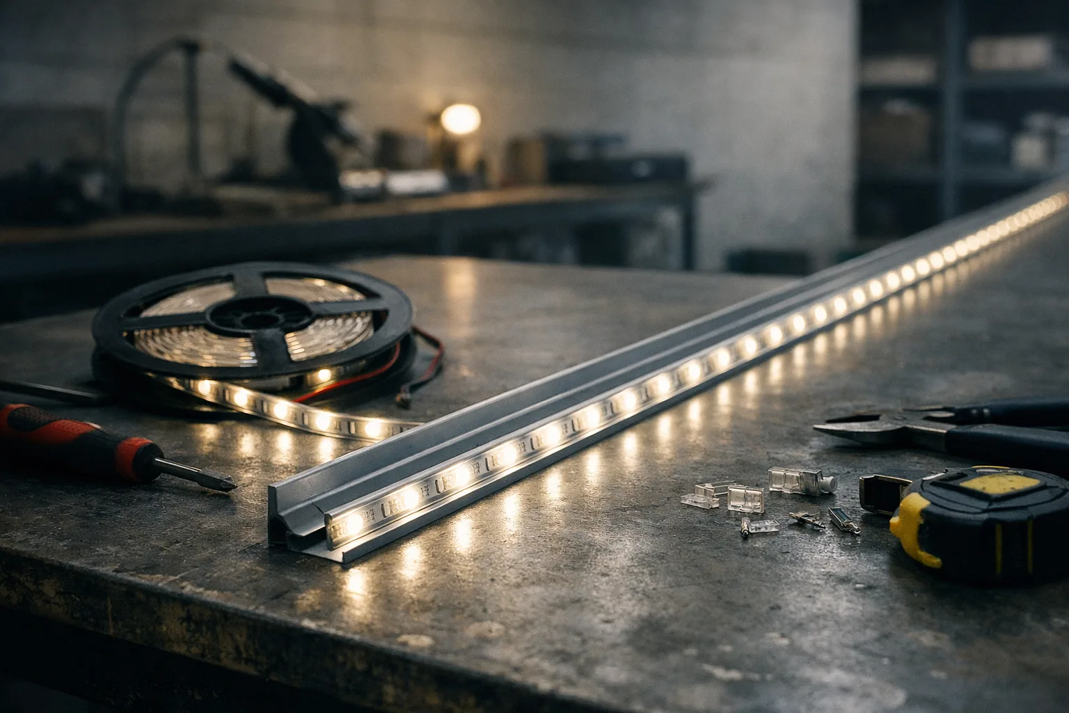
Strip is constant-voltage product because it is cut to length on site, which is the first of the four questions in constant current or constant voltage — and the voltage drop below is the price of that choice.
The two questions on every constant-voltage strip installation are how big the supply needs to be and how long a run can be fed from one end. The first is arithmetic. The second is where most installations go wrong, because the drop happens along the strip itself, not just in the cable feeding it.
Calculator
The formulae
Why the far end goes dim and slightly warm-shifted
Constant-voltage strip is a chain of segments, each with its own series resistor setting current. Segment current depends on the voltage present at that segment. Voltage falls along the run, so segments near the far end run at lower current than those at the feed — the strip gets progressively dimmer along its length.
On white strip this reads as a gradient that is obvious once pointed out and hard to unsee, particularly in a continuous cove where the eye has the whole run in view. On RGB or tunable strip it is worse: the three channels do not respond identically to reduced drive, so the far end shifts in colour as well as brightness, and no controller setting can correct it because the difference is along the strip rather than between channels.
Keep total drop under about 5% of nominal for uniform appearance; 10% is usually visible. Doubling the supply voltage halves the current for the same power, and drop is proportional to current — so a 24 V strip drops roughly half as much as a 12 V strip over the same run. That, not efficiency, is the main argument for 24 V and 48 V systems.
The four fixes, in order of preference
- Feed from both ends. Free if the supply is positioned sensibly. Halves the effective run length and quarters the drop, because each half now carries half the current over half the distance.
- Inject power at intervals. Run a heavier cable alongside the strip and connect it every couple of metres. The strip's own thin conductors then carry current only over short distances. Standard practice on long coves.
- Use a higher system voltage. 24 V instead of 12 V, or 48 V for long architectural runs. Check that the strip and controller support it.
- Split into separately fed sections. Independent supplies per section, which also limits the failure to one section.
What this calculator does not check
- Constant-current strip. Everything here assumes constant voltage. A CC-driven strip behaves differently — see driver matching.
- Thermal derating. Strip in an unventilated aluminium-free channel runs hot, which shortens life and shifts colour. Power per metre is not the whole story; the profile and its heatsinking matter.
- Conductor heating. High current density in a thin strip conductor raises its temperature, which raises its resistance, which increases the drop — a mild positive feedback this linear model ignores.
- Inrush. Several supplies energised together can trip a breaker on inrush even when the running current is trivial; the mechanism is described in the driver note.
- Cable sizing for safety. The cross-section here is used only to compute voltage drop. Current-carrying capacity, protection and installation method are matters for the wiring regulations in your jurisdiction, not for a web calculator.
Sources and further reading
- Copper resistivity 0.0175 Ω·mm²/m at 20 °C — standard value for annealed copper; resistance rises roughly 0.4% per °C above that.
- Strip datasheets for the conductor resistance per metre. Where it is not published, measure it: the resistance of the copper rails end to end on an unpowered length, divided by that length.
- Your national wiring regulations for extra-low-voltage circuit design and conductor sizing.