Selection & calculation
Choosing a dimming protocol: 0–10 V, DALI-2, DMX512, phase-cut and wireless
What each dimming interface can and cannot do, the wiring and topology mistakes that break each one, why commissioning labour rather than hardware cost usually decides, and the boundaries where one protocol stops being the right answer.
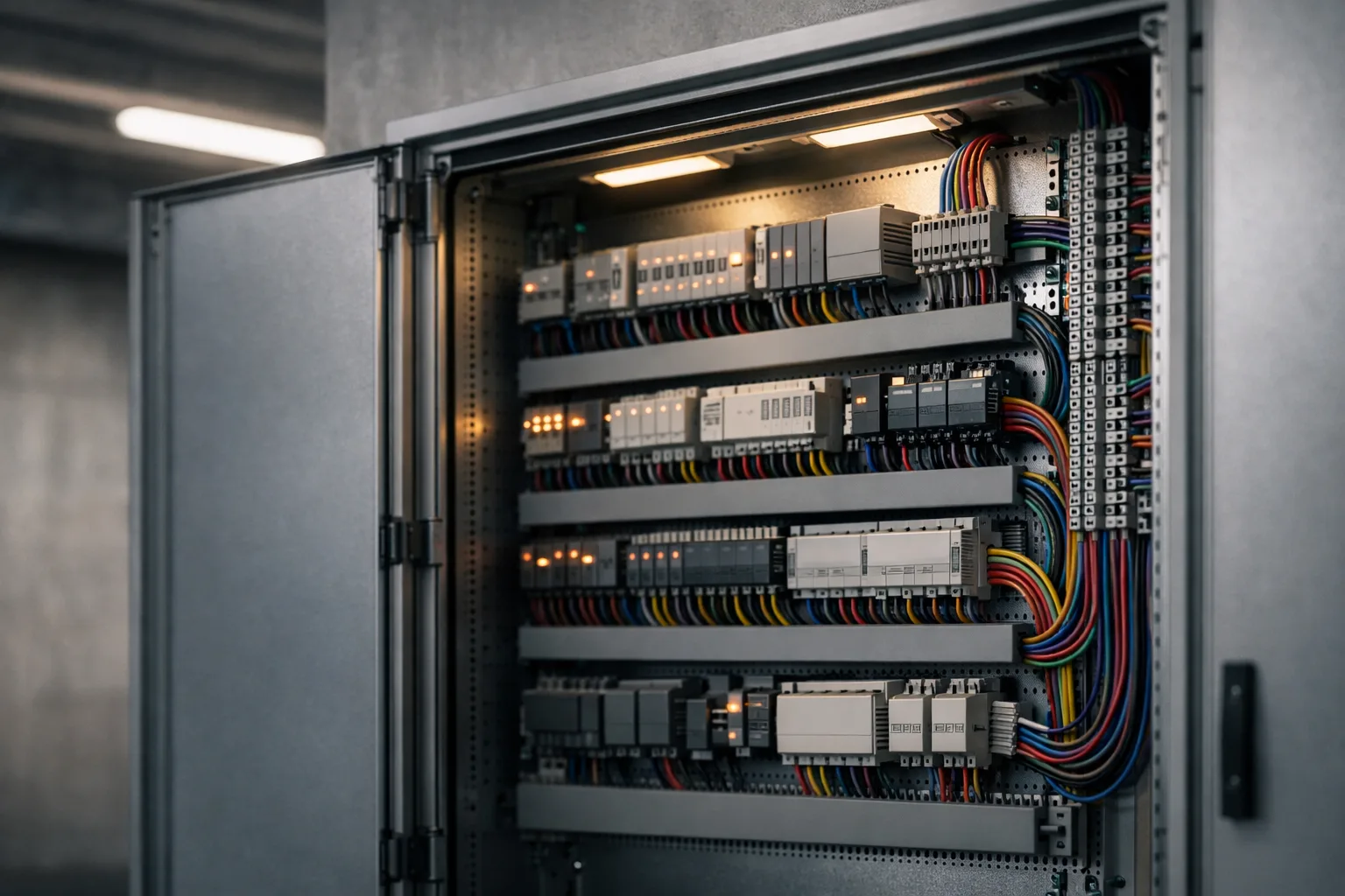
Dimming interface decisions are usually made on hardware cost, which is the one factor that barely matters. The interface determines how the installation is commissioned, whether it can be reconfigured after handover, and whether a fault can be diagnosed from a laptop or requires someone on a ladder. Those are the costs.
The five options, compared on what actually differs
| Interface | Addressable | Feedback | Commissioning | Wiring |
|---|---|---|---|---|
| 0–10 V / 1–10 V | No — a channel is a wire pair | None | None beyond wiring it correctly | Extra pair per channel, polarity-sensitive |
| DALI-2 | Yes — per luminaire | Yes — lamp failure, level, energy | Required; addressing and grouping is a real task | Two-wire bus, topology-free |
| DMX512 | Yes — per channel | None | Set start addresses on each device | Daisy chain with termination |
| Phase-cut (triac / trailing edge) | No | None | None | Uses the existing switch wire |
| Wireless mesh | Yes | Yes, usually | App-based; usually the fastest | Power only |
0–10 V: the failure is always the same two things
An analogue control voltage sets the level. It is cheap, it is robust, and almost every failure is one of two mistakes.
Source versus sink. In the standard architectural arrangement the driver supplies the current and the controller sinks it — the control device is essentially a variable resistor pulling the line down. Some equipment instead expects to have a voltage driven at it. Connect a sinking controller to a driver expecting a source and the result is a channel stuck at full, stuck at minimum, or behaving erratically. The datasheets both say "0–10 V" and they are not compatible.
Polarity and voltage drop. The control pair is polarised, and reversing it does nothing useful. Then, because it is an analogue signal, its voltage drops along the run exactly as any other conductor does. On a long circuit with many drivers sinking current, fittings at the far end sit at a measurably different control voltage from those at the near end — and dim to a visibly different level. The symptom is a row of lights that track together at full output and spread out at 20%.
Fixed zones that will never be regrouped, no need for status reporting, a cost-sensitive project, and short control runs. A warehouse with three zones and a wall panel does not need a digital bus. Specify the control wire cross-section against the run length rather than defaulting to the thinnest cable that fits.
DALI-2: the protocol whose cost is labour
Where the fitting changes colour as well as level, the channel count and the DALI device type become part of this decision rather than a later detail — see tunable white, dim-to-warm and full colour.
DALI is a digital two-wire bus. Each device on it has an address, can be put into groups and scenes, and can report back — lamp failure, current level, and with the D4i extension, energy and diagnostic data from inside the luminaire. DALI-2 (IEC 62386) tightened certification to cover control devices such as sensors, which is what made multi-vendor systems reliably interoperable; DALI-1 era equipment varied enough that mixing brands was a gamble.
Three constraints that get designed past and then discovered:
- Addresses per bus. A single DALI bus segment addresses 64 control gear devices. A large floor needs multiple segments and an application controller above them. Counting luminaires late and discovering the sixty-fifth is a bad afternoon.
- Bus power budget. The bus power supply delivers a limited current and every device consumes a share of it. Sensors and input devices count too. Exceeding the budget produces intermittent, maddening faults rather than a clean failure.
- Cable length. There is a maximum bus length driven by voltage drop on the pair, and it assumes a reasonable conductor size. Long runs need either a larger cross-section or another segment.
The real cost of DALI is not the gear. It is that someone has to commission it: address every luminaire, assign groups, build scenes, bind sensors, and document the result. That is a skilled day or several. Two things follow. First, put commissioning in the tender explicitly, or you will receive a DALI installation running at default settings — which behaves like an expensive switch. Second, insist on the commissioning file being handed over. Without it, the next person to modify the layout starts from nothing.
DMX512: right for effect, wrong for a building
DMX512 was designed for stage lighting: a fast, unidirectional stream of level data over RS-485, 512 channels to a universe. For colour-changing and effect work its refresh rate and per-channel directness are exactly right, and it remains the correct choice for façade lighting, feature colour and anything synchronised to media.
For general building lighting it is a poor fit — no feedback, no groups maintained by the devices themselves, and every fixture needs a start address set correctly. Its two classic installation faults are worth stating because they are so consistent:
- Star topology. DMX is a daisy chain. Splitting the cable to feed two branches from one point causes reflections and intermittent flicker that nobody can reproduce on demand. Use a proper splitter/repeater.
- No terminator. The chain needs a 120 Ω termination at the far end. Without it the installation often works — until the run gets longer or the ambient noise changes, and then it does not.
Phase-cut: a retrofit compromise, not a specification
Cutting the mains waveform with a triac (leading edge) or a MOSFET (trailing edge) lets an existing wall dimmer control an LED load with no new cabling. That is its entire advantage and it is a real one for refurbishment where the wiring cannot change.
Against it: dimmers have a minimum load below which they misbehave, and an LED load is a small fraction of the incandescent load the dimmer was designed for, so a room whose lamps have all been swapped can drop under it. Leading- and trailing-edge dimmers are not interchangeable for a given driver. Low-end performance is generally poor, with visible steps, drop-out or flicker near the bottom. And compatibility is a property of the specific dimmer-plus-driver pair, which is why manufacturers publish compatibility matrices — check the pairing you will actually install, not the brand.
If the cabling is being installed anyway, the marginal cost of a control pair or a DALI bus is small, and every limitation above disappears. Phase-cut in a new installation is a decision that will be regretted at the first reconfiguration.
Wireless mesh: fastest to commission, longest to live with
Bluetooth mesh, Zigbee and the various proprietary systems remove the control cable entirely. For refurbishment in an occupied building — where running a bus means ceilings, disruption and out-of-hours access — that advantage is decisive, and app-based commissioning is genuinely quicker than addressing a wired bus.
The questions to ask are all about the decade after handover:
- Who owns the commissioning data? If the configuration lives only in one contractor's account, you have a dependency, not an installation.
- What happens when the app is discontinued? Lighting outlives mobile software by a wide margin. Ask what the fallback control is.
- Is it a standard or a brand? A certified Bluetooth mesh or Zigbee implementation gives some prospect of replacement devices in ten years. A proprietary radio gives you one supplier for the life of the building.
- What is the RF environment? Dense metal racking, lift shafts and heavy 2.4 GHz congestion all degrade mesh reliability, and a site survey costs less than discovering it after installation.
Choosing, in one pass
- Will the space be reconfigured, or does it need per-luminaire status? → DALI-2, and budget the commissioning.
- Fixed zones, no feedback needed, cost-driven? → 0–10 V, with the control conductor sized for the run.
- Colour, effect or media synchronisation? → DMX512, daisy chained and terminated.
- Occupied building, no new cabling possible? → wireless, with the ownership and longevity questions answered in writing first.
- Existing dimmers that must stay? → phase-cut, against the manufacturer's compatibility matrix for that exact pairing.
Whatever the answer, the flicker requirement follows the dimming range, not just full output — see the note on flicker for why a fitting can pass at 100% and fail badly at 10%.
Sources and further reading
- IEC 62386 — the DALI standard series, including the DALI-2 parts covering control devices.
- IEC 60929 Annex E — the 1–10 V control interface for electronic ballasts, the origin of the source/sink convention.
- ANSI E1.11 (DMX512-A) — the entertainment lighting data protocol, its topology and termination requirements.
- Manufacturers' dimmer/driver compatibility matrices — the only reliable source for a phase-cut pairing.