Metrics & standards
Flicker: what PstLM and SVM measure, and why a phone camera is only a screening tool
The two regulated flicker metrics, the driver topologies that cause failures, why the stroboscopic effect matters more than visible flicker in workshops, and an honest account of what a slow-motion phone video can and cannot tell you.
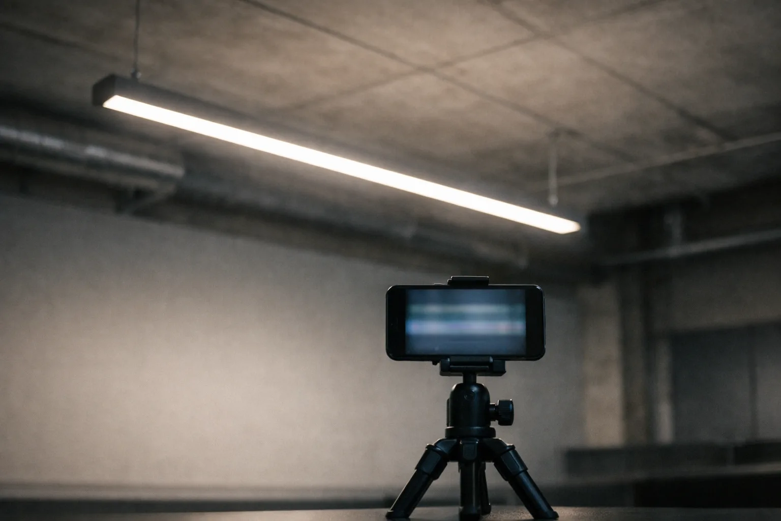
Flicker is the defect most likely to be discovered after installation, because it is invisible on a datasheet, invisible in a showroom, and — in the frequency range that causes the most complaints — invisible to direct vision. It shows up as headaches in an office and as apparently stationary rotating machinery in a workshop.
Two different phenomena, two different metrics
Light output from a mains-driven source is never perfectly steady. What matters is the depth and frequency of the modulation, and there are two distinct effects with different thresholds.
| Phenomenon | Roughly | Metric | Limit | What it feels like |
|---|---|---|---|---|
| Visible flicker | below ~80 Hz | PstLM | ≤ 1.0 | Perceived directly as fluctuation; eyestrain, headache |
| Stroboscopic effect | ~80 Hz to ~2 kHz | SVM | ≤ 0.4 | Not seen in static scenes; moving objects appear frozen, multiplied or stuttering |
PstLM is a short-term flicker indicator adapted for lighting, defined in IEC TR 61547-1. A value of 1.0 is calibrated to the threshold of perception for a standard observer, so ≤ 1.0 means "at or below the point where a typical person notices".
SVM — stroboscopic visibility measure, CIE TN 006 — targets the higher-frequency range. Again 1.0 is nominally the perception threshold; the regulatory limit of 0.4 sits well below it because the consequence in an industrial setting is not discomfort but a lathe chuck that appears to be stopped.
Visible flicker is unpleasant. The stroboscopic effect is dangerous, and it is specifically dangerous around rotating and reciprocating machinery, where it can make a moving part look stationary. If you are lighting a workshop, a machine shop or any space with exposed rotating equipment, SVM is the number to hold the supplier to — and it is the one least likely to appear on a quotation.
The older percent-flicker view, and IEEE 1789
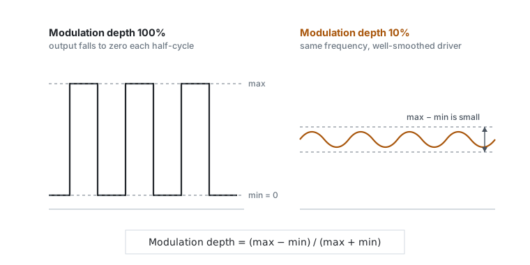
Before the regulated metrics, flicker was usually described by modulation depth:
IEEE 1789-2015 pairs this with frequency to define low-risk and no-observable-effect regions: as frequency rises, a much greater modulation depth becomes acceptable. Below about 90 Hz the permitted depth becomes very small indeed. The document is a recommended practice rather than a regulation, but it remains the clearest way to explain to a non-specialist why "it only ripples 20%" is a meaningless statement without the frequency attached.
Where flicker comes from, in order of how often we see it
1. Ripple straight from the rectified mains
An AC-direct or "driver-on-board" topology — LEDs driven from rectified mains with minimal energy storage — is cheap, compact, and has no electrolytic capacitor to dry out. It also passes the mains ripple almost undiminished into the light output, producing very deep modulation at twice the mains frequency (100 Hz on a 50 Hz supply, 120 Hz on 60 Hz). This is the single most common cause of a flicker failure, and it is a design decision, not a fault.
2. Low-frequency PWM dimming
Dimming by pulse-width modulation is fine if the carrier is high enough. Carriers in the low hundreds of hertz cost less and are common in inexpensive controllers. The trap is that the modulation depth at PWM dimming is by definition 100% — the LED is fully on or fully off — so everything depends on the frequency. A fitting can be perfectly acceptable at full output and fail badly at 20% dim, which is why flicker has to be checked across the dimming range and not only at 100%.
3. Driver and dimmer incompatibility
A phase-cut (triac) dimmer feeding a driver that was not designed for one produces erratic conduction, and the resulting output can flicker, shimmer at the bottom of the range, or drop out entirely. This is an interaction failure: both components can be individually compliant. It is why compatibility lists exist and why they must be checked for the specific pairing — and it is the strongest practical argument for choosing a dimming protocol deliberately rather than inheriting whatever is already on the wall.
4. Ageing electrolytics
Where a driver relies on an electrolytic capacitor for smoothing, its capacity falls as it dries out, and it dries out faster when hot. A fitting that measured well on day one can develop visible ripple after a few years in a hot ceiling void. This is one of the arguments for caring about driver case temperature even when the LED itself is comfortably within limits.
What a phone camera can and cannot tell you
The standard field trick is to record the light in slow motion on a phone and look for banding. It is genuinely useful and it is not a measurement. Being precise about the difference:
| Question | Phone slow-motion | Photometric head + logger |
|---|---|---|
| Is there gross low-frequency modulation? | Usually reveals it | Yes |
| Comparing two fittings side by side | Reasonable, same camera same settings | Yes |
| Does it meet PstLM ≤ 1.0? | No | Yes |
| Does it meet SVM ≤ 0.4? | No | Yes |
| Behaviour across the dimming range | Indicative only | Yes |
Three specific reasons the phone cannot produce a compliance figure:
- Rolling shutter. The banding you see is an artefact of the sensor scanning line by line. Its spacing depends on the readout rate as much as on the light, so band spacing is not a frequency measurement.
- Aliasing. Frame rate and flicker frequency beat against each other. A 120 Hz modulation recorded at 240 fps can look completely steady. Absence of banding is not evidence of absence of flicker.
- No photometric calibration. Automatic exposure and gain are adjusting continuously, and the camera's response is not linear in luminance, so you cannot recover modulation depth from image brightness.
Used honestly, the phone answers one question: is this obviously bad? If bands are strong and stable, stop and get it measured. If they are absent, you have learned very little.
Putting it in a specification
Three lines, and the third is the one usually missing:
- PstLM ≤ 1.0 and SVM ≤ 0.4 at full output, per IEC TR 61547-1 and CIE TN 006, evidenced by test report rather than declaration.
- The same limits maintained across the whole dimming range, stated at specific set points — 100%, 50%, 20%, 10% — because PWM-dimmed product commonly passes at one and fails at another.
- The driver and control gear model actually supplied named on the report. A flicker result belongs to a luminaire-plus-driver-plus-dimmer combination, and substituting an equivalent driver during value engineering invalidates it.
Fixing flicker that is already installed
Specification limits help on the next project. When the complaint is about a building that is already occupied, the order of investigation below resolves most cases without replacing luminaires, and it is worth working through it before accepting a supplier's offer to swap the fittings.
- Establish whether it happens at full output. If the installation is clean at 100 % and only visible when dimmed, the driver and the dimmer are the subject, not the luminaire. This single observation eliminates most of the possibilities and costs nothing.
- Check the dimmer pairing before anything else. A phase-cut dimmer driving a driver that was never validated against it is the most common cause we see, and the fix is usually a different dimmer rather than a different fitting. Manufacturers publish compatibility matrices for exactly this; see the note on dimming protocol selection for why a leading-edge and a trailing-edge dimmer are not interchangeable.
- Check the load against the dimmer minimum. A circuit that has been partially decommissioned, or where a lumen-for-lumen retrofit dropped the connected load by 60 %, can fall below the dimmer's minimum load and flicker at the bottom of its range for that reason alone.
- Look for a shared circuit with a large intermittent load. Voltage dips from lift motors, compressors or welding plant modulate the supply, and the lighting is the visible symptom rather than the cause. A logger on the distribution board over a working day will show it.
- Only then consider the driver. Where the driver is genuinely the source, replacing it with a constant-current unit of the same output rating but a different topology is usually cheaper than replacing luminaires — provided the compliance window still matches the module, which is what the driver compliance window calculator is for.
One caution on measurement during a dispute. If you take readings to support a claim, take them at the same dim set points, on the same circuit, with the same instrument, before and after any change. A PstLM figure with no stated set point and no stated supply condition is not comparable with anything, including a later reading of the same installation.
Sources and further reading
- IEC TR 61547-1 — measurement method for PstLM.
- CIE TN 006:2016, Visual Aspects of Time-Modulated Lighting Systems — definition of the stroboscopic visibility measure.
- Commission Regulation (EU) 2019/2020, Ecodesign requirements for light sources — the PstLM ≤ 1.0 and SVM ≤ 0.4 limits and their application date.
- IEEE 1789-2015, Recommended Practices for Modulating Current in High-Brightness LEDs for Mitigating Health Risks to Viewers — the frequency-versus-modulation-depth risk regions.