Metrics & standards
The average passed and the desk is dark: uniformity, Uo and the measurement grid
Why an installation can hit its average illuminance and still fail, what Uo is actually the ratio of, how the area you average over decides the answer, spacing-to-height ratio, and the three clauses that make uniformity verifiable on site.
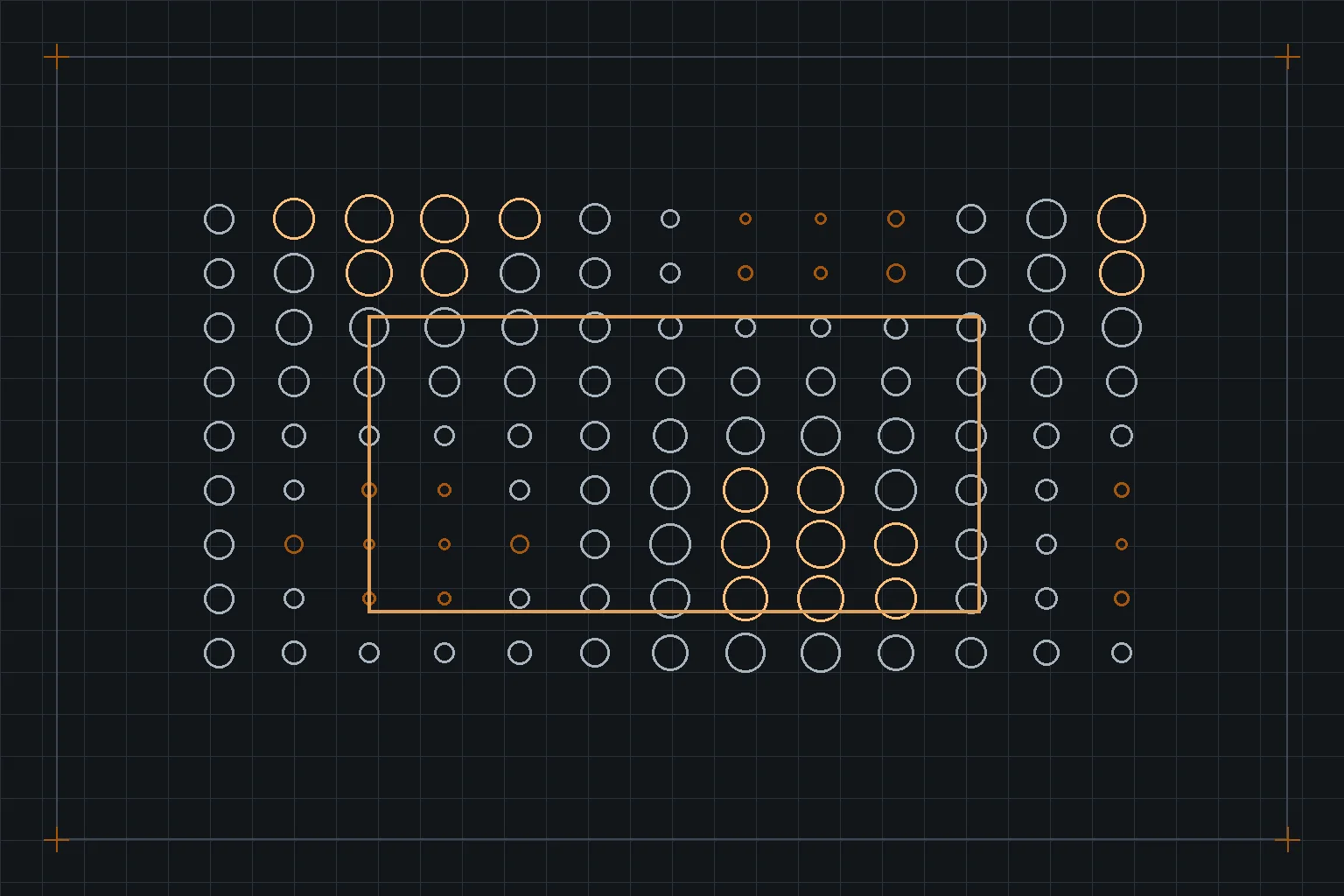
An office is handed over at an average of 512 lx against a 500 lx specification. The contractor's calculation says compliant, the commissioning readings say compliant, and two people near the window wall are working at 280 lx under a fitting spacing that never suited the room. Nobody has falsified anything. The specification asked for an average and got one.
What Uo is the ratio of
Uniformity in EN 12464-1 is Uo, the ratio of the minimum illuminance to the average illuminance, and the whole content of the requirement is in the words that follow it: over the task area. Change the area you average over and you change both terms of the ratio.
This is where most disputes live. A contractor who computes the average over the whole room floor includes the space under every fitting and the corridors of light between them, and gets a comfortable number. The specification meant the area where the work happens — the desks, the bench, the aisle — which is smaller, positioned where the furniture went rather than where the grid is regular, and often sits at the unluckiest part of the layout. Two honest calculations, two different answers, because the area was never defined.
EN 12464-1 structures a space into a task area, an immediately surrounding area and a background area, each with its own illuminance and uniformity requirement, precisely so that "the room" is never the unit of assessment. The relationship between them, and why the maintained value differs from the calculated one, is set out in maintained versus initial illuminance.
The grid decides the minimum
Uo has a minimum in it, and a minimum is only as low as your sampling finds. A calculation on a coarse grid never lands on the darkest point; a calculation on a grid whose spacing happens to align with the luminaire pitch can sample every cell at the same phase of the light pattern and report a uniformity the room does not have.
The standard handles this by defining the grid rather than leaving it to the person doing the calculation: cell size derives from the dimensions of the area being assessed, with an upper bound, and the grid is required to avoid coinciding with the luminaire spacing. Take the current rule from the edition your contract names — it has changed between editions, and it is one of the places where quoting a remembered figure gets people into trouble.
Two practical consequences. First, a lighting calculation submitted without its grid visible is not checkable, and should be returned. Second, when you verify on site, use the same grid as the calculation. Comparing a nine-point site measurement against a several-hundred-point calculated grid is comparing two different quantities, and the site figure will usually look better than the truth.
Spacing to height, and why scallops appear
Uniformity is mostly decided before any of this, by the relationship between how far apart the fittings are and how far they are above the working plane. Every luminaire distribution has a spacing-to-height ratio beyond which its beams stop overlapping sufficiently at the working plane, and it is published in the photometric data. Exceed it and you get scallops: bright patches under the fittings, dark bands between them, an average that is fine and a Uo that is not.
The ratio is a property of the distribution, not of the fitting's size or wattage, which is why swapping a fitting for a nominally equivalent one with a narrower beam during value engineering can wreck a layout that was designed correctly. This is the single most common way a retrofit that met its lumen target still fails on site — the mechanism is worked through in illuminance shortfall after retrofit.
A worked check you can do on a submitted calculation
You do not need the software to sanity-check a claim. Take the calculation's own figures:
Uo = Emin / Eave
Example, over a stated task area: Emin = 210 lx, Eave = 520 lx
Uo = 210 / 520 = 0.40 — against a typical office requirement of 0.60, this fails, despite the average being 4 % above target.
Then ask three questions of the sheet: what area was the average taken over, what grid was used, and where in the room is Emin. If the answer to the third is "in a corner behind a column", the number may be defensible. If it is in the middle of a desk run, the layout is wrong regardless of what the average says.
"Uo ≥ 0.6" written without naming the area it applies over can be met by choosing a convenient area after the fact. The area, the grid and the reference plane height belong in the same sentence as the number.
What changes between calculation and building
Three things move the site figure away from the calculated one, and all three are worth anticipating rather than arguing about at handover.
- Surface reflectances. Calculations are run with assumed ceiling, wall and floor reflectances. A dark feature wall, a glazed elevation at night or grey carpet instead of the assumed light one removes inter-reflected light, and inter- reflected light is disproportionately what fills the gaps between fittings — so reflectance error hits uniformity harder than it hits the average.
- Furniture and partitions. High storage and screens installed after the lighting design cast exactly the shadows the calculation's empty room did not have.
- Position tolerance. Ceiling grid modules, structural constraints and services coordination move fittings from where the calculation put them. A layout that only just met its spacing-to-height ratio has no margin for that.
Three clauses that make uniformity enforceable
- Uo stated with the area it applies over, the reference plane height, and the requirement that task areas be located on the drawing rather than assumed to be the whole floor.
- The calculation grid shown in any submitted lighting calculation, with the reflectances and maintenance factor used printed on the same sheet.
- Site verification on the same grid as the calculation, at the same reference plane, with the measurement conditions recorded — meter class, stabilisation time and the treatment of daylight. Without that last clause the acceptance reading is not comparable with the thing it is supposed to verify.
Sources and further reading
- EN 12464-1 — lighting of indoor work places; task/surrounding/background structure, uniformity requirements by application, and the grid rules for assessment.
- EN 12464-2 — the outdoor work places counterpart, with its own uniformity treatment for areas where the task is not a plane.
- CIBSE Code for Lighting and the SLL Lighting Handbook — spacing-to-height ratio, room index and the practical layout rules behind the arithmetic.
- CIE 97 — maintenance factor, and therefore the relationship between a calculated figure and a maintained one.