Metrics & standards
Why a luminaire marked "UGR<19" still glares in your room
UGR is a property of a room, an observer position and a viewing direction — not of a luminaire. What the catalogue figure actually assumes, the conditions under which the method is not valid at all, and why fluorescent-to-LED retrofits generate glare complaints at identical lumen output.

"UGR<19" printed on a luminaire datasheet is one of the most widely misunderstood claims in lighting procurement. It is not wrong, exactly. It is an answer to a question about a room you are not building.
UGR describes a situation, not a product
The Unified Glare Rating is computed from what an observer's eye actually receives, at a specific place, looking in a specific direction:
Read the variables and it is obvious that a luminaire alone cannot have a UGR. The sum runs over every fitting the observer can see. Lb depends on the room's surface reflectances. ω depends on mounting height and distance. p depends on where the observer is sitting and which way they face. Change the ceiling height, change the answer.
What the catalogue number actually assumes
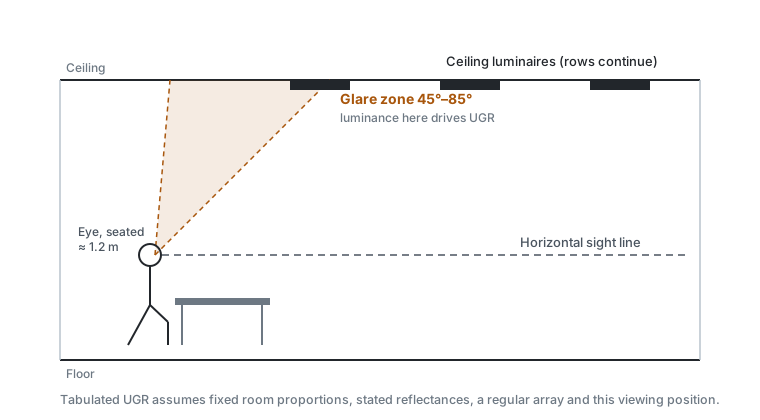
Manufacturers publish UGR using the CIE tabular method, which evaluates the luminaire in a reference room — a standardised empty rectangular space with specified surface reflectances (commonly 0.70 ceiling, 0.50 walls, 0.20 floor), a regular array of the fittings, a stated mounting height, and observers at defined positions looking along and across the array. The published figure is normally the worst case across that table.
That is a reasonable, comparable basis. It is also a room with white walls, no furniture, no partitions and no glazing. The specific ways your room differs all push the same direction:
| Real condition | Effect on the UGR equation |
|---|---|
| Dark walls, exposed dark ceiling, dark floor finish | Lb falls, and it sits in the denominator — the whole bracket rises |
| Lower mounting height than the reference case | ω rises with the square of proximity, and ω is a direct multiplier |
| Observer faces along the array rather than across it | Different p for every fitting; the "worst direction" may not be the one tabulated |
| Irregular layout, or fittings concentrated over a walkway | The tabular method assumes a regular array and no longer applies |
| Seated observer, screen-based work, upward gaze | More fittings enter the field of view at low position index |
Where the method is not valid at all
This is the part that gets left out of datasheets. The CIE tabular UGR method has a validity range for the solid angle subtended by the luminous part — approximately 0.0003 sr to 0.1 sr. Outside it the formula is not meant to be applied.
- Very large luminous areas — big diffusing panels, luminous ceilings, coves — exceed the upper bound. UGR is not the right tool; the standard points you at other treatments for large-area sources. A "UGR" quoted for a 2 m² luminous ceiling panel is a number produced by feeding the formula input it was not built for.
- Very small, very bright apertures — a bare high-power LED behind a small lens — can fall under the lower bound, and the rating underestimates what people actually experience because the metric was calibrated on sources with more visual extent.
- Single luminaires and asymmetric layouts break the array assumption underlying the tables.
The second and third cases are exactly what modern LED downlights and linear optics look like, which is why the glare complaint rate on LED retrofits is higher than the paperwork predicts.
The retrofit failure, in one comparison
The classic complaint arrives after a lumen-for-lumen replacement, and the mechanism is a change in luminance, not in light output.
Consider replacing a recessed fluorescent modular fitting — a large, opal-diffused aperture — with an LED panel or, worse, with a set of LED downlights delivering the same total flux into the same space. Total lumens unchanged. Illuminance on the desk unchanged. The meter says the job is identical.
But luminance is flux per unit area per unit solid angle. Take a given output and emit it through a much smaller aperture, and source luminance rises by roughly the ratio of the areas. In the UGR sum, that term is squared. The glare contribution can rise by an order of magnitude while the illuminance reading does not move at all.
Not "what is the UGR?" but: at what luminance does the aperture run, and over what area? Two fittings with identical output and identical published UGR can differ by a factor of five in aperture luminance, and that difference is what the occupant actually experiences.
Making it a specifiable requirement
EN 12464-1 sets a limiting value, UGRL, per application, and requires that the installation be evaluated for the relevant viewing directions. Three things turn that into something enforceable:
- Require a project UGR calculation, not a product figure. Ask for UGR computed in the actual room geometry, with the actual reflectances, at stated observer positions and in stated viewing directions. Any competent lighting calculation package produces this. If a tenderer returns a catalogue number instead, they have not run the calculation.
- State the reflectances you will actually have. If the architect has specified a dark ceiling, say so in the brief. A calculation run at 0.70 ceiling reflectance against a finished surface at 0.30 is worthless, and this substitution happens constantly.
- Name the viewing directions. For open-plan desking, both along and across the array. For a room where people sit facing a screen wall, that direction specifically. The worst direction is not always the one the tabular method reports.
What UGR does not cover
It says nothing about how evenly the light lands, which is a separate requirement with a separate failure mode — see uniformity and the compliant average. The glare control that gets a fitting under a UGR limit also costs output, and therefore costs lighting power density, which is where the two requirements pull against each other.
Two adjacent problems are outside the metric and need separate treatment.
Reflected glare on screens and glossy surfaces is a different mechanism — a bright source mirrored in the work surface. It is governed by the luminance of the fitting at high emission angles, which is why the older screen-based-work luminance limits exist. A fitting can have an excellent UGR and still be plainly visible reflected in a monitor.
Discomfort from high contrast within the field of view — brilliant fittings against a dark ceiling — is real even at compliant UGR. Raising ceiling and wall illuminance, which the 2021 revision of EN 12464-1 makes explicit, reduces it by lifting Lb. That is a design response, not a product selection.
Sources and further reading
- CIE 117, Discomfort Glare in Interior Lighting — the origin of the UGR formula, the tabular method and its stated range of validity.
- CIE 190, Calculation and Presentation of Unified Glare Rating Tables — how manufacturers' published tables are produced, and the reference room conditions they assume.
- EN 12464-1 — UGRL limiting values by application and the requirement to evaluate relevant viewing directions.
- Guth, S. K. (1963), A method for the evaluation of discomfort glare — the position index p.